Cables and connections
We recommend using balanced input wiring; however, unbalanced input wiring is also supported. For detailed instructions, please refer to our amplifier input wiring application note.
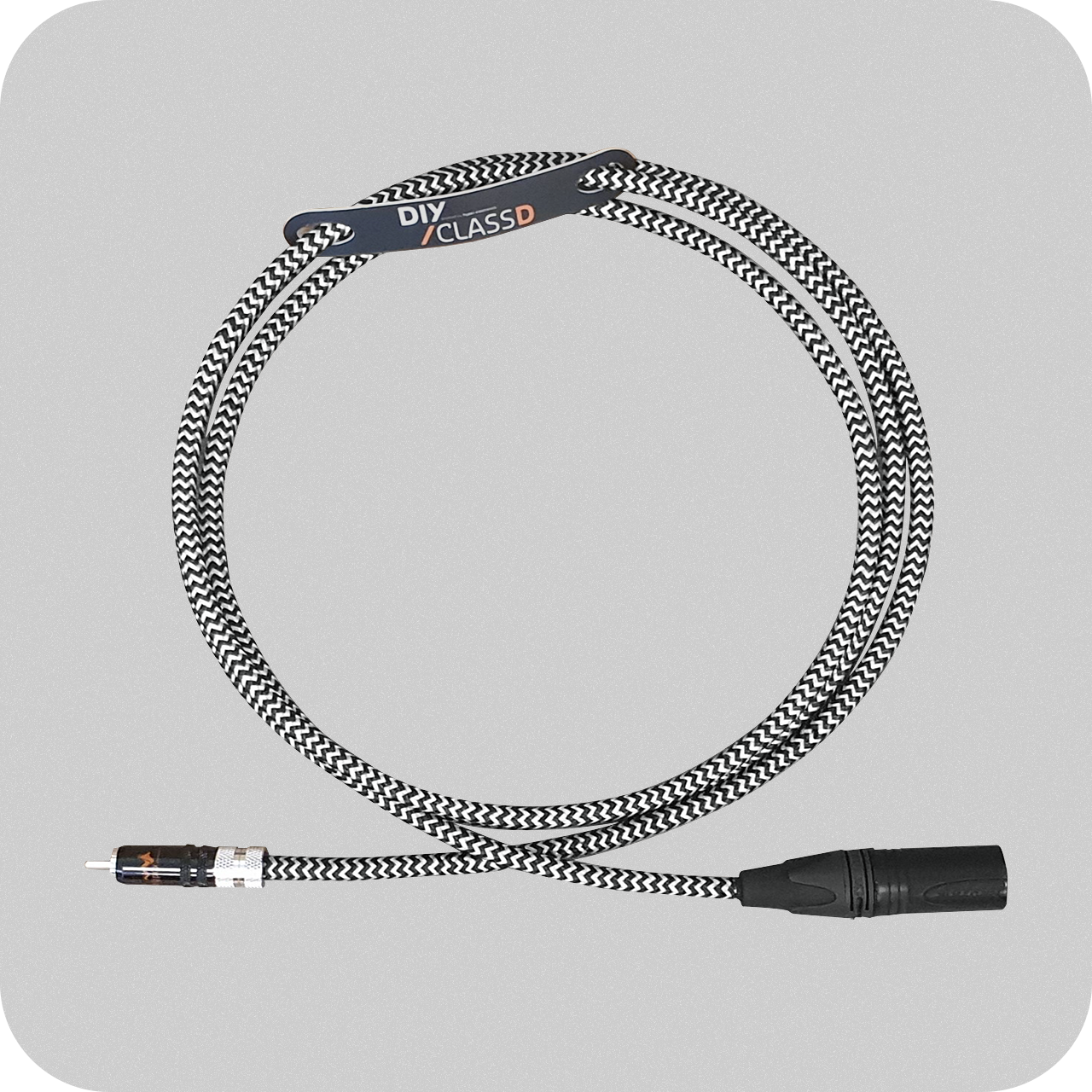
To convert an unbalanced input signal to a balanced one, a high-quality interconnect cable can be used. Ready-to-use interconnect cables are available at www.diyclassd.com.
This setup essentially functions as a source selector. For detailed instructions on wiring an RCA connector to the UcD module, please refer to our application note "Dealing with Legacy Pin 1 Problems".
To implement the setup, install a DPDT switch to connect the hot and cold inputs of the UcD module to either pins 2 and 3 of the XLR connector or the signal and shell contacts of the RCA connector. Note that pin 1 of the XLR connector remains hardwired to the chassis and is not switched. Similarly, the RCA shell contact remains hardwired to the chassis.
When the DPDT switch is set to RCA, the cold input of the UcD module is grounded via the RCA connector. For further details, refer to the schematic in the "Dealing with Legacy Pin 1 Problems" application note.
Fundamentally, there is no inherent issue with using tube preamplifiers. However, many tube preamplifiers are designed to pair with tube power amplifiers, which are typically AC coupled. Consequently, some tube preamplifiers lack the necessary safeguards against turn-on and turn-off transients.
In certain cases, these preamplifiers may output their full anode voltage during power cycling. This can cause significant stress on connected equipment, as we have observed that a notable number of repairs result from tube preamplifiers discharging their output capacitors into the UcD™ input circuitry. It is important to note that such behavior is problematic for most solid-state amplifiers, not just UcD™ or NCORE® models.
We offer cable sets specifically designed for connections between the amplifier and the SMPS. Additionally, the datasheets for each product provide detailed pinout information for every connector on the module.
For our DIY amplifier modules, wiring schematics are available on our website at www.diyclassd.com.

